Line in,
valve warmth out.
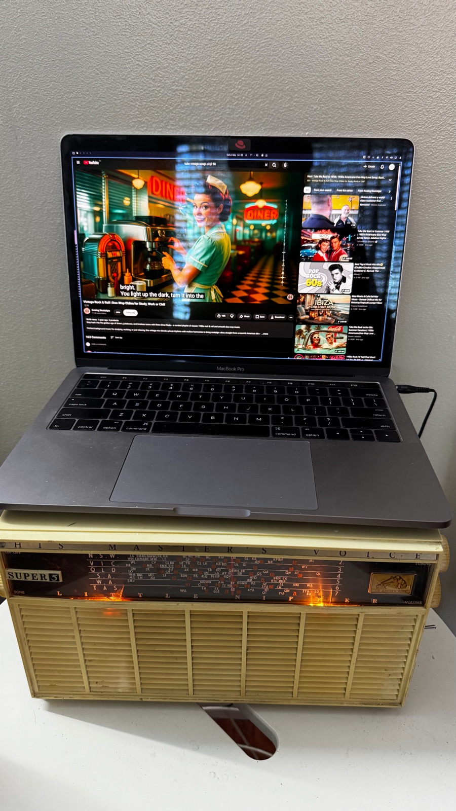
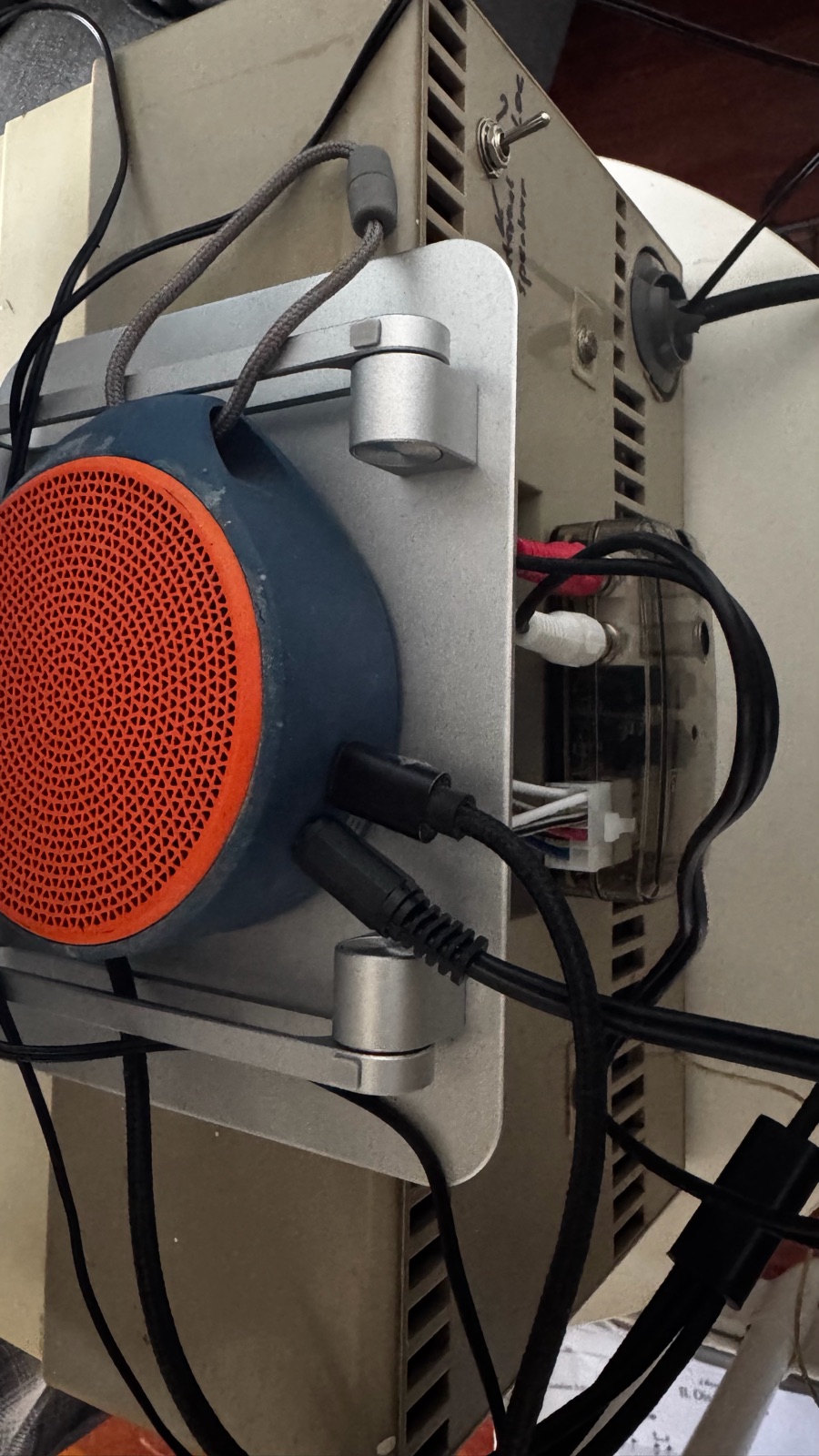
How a mid-century Australian five-valve mantel radio gained a 3.5 mm AUX input and a switchable line output to a Yamaha amplifier. The original tuner and speaker still work as before, and two toggle switches choose the source and where the sound goes.
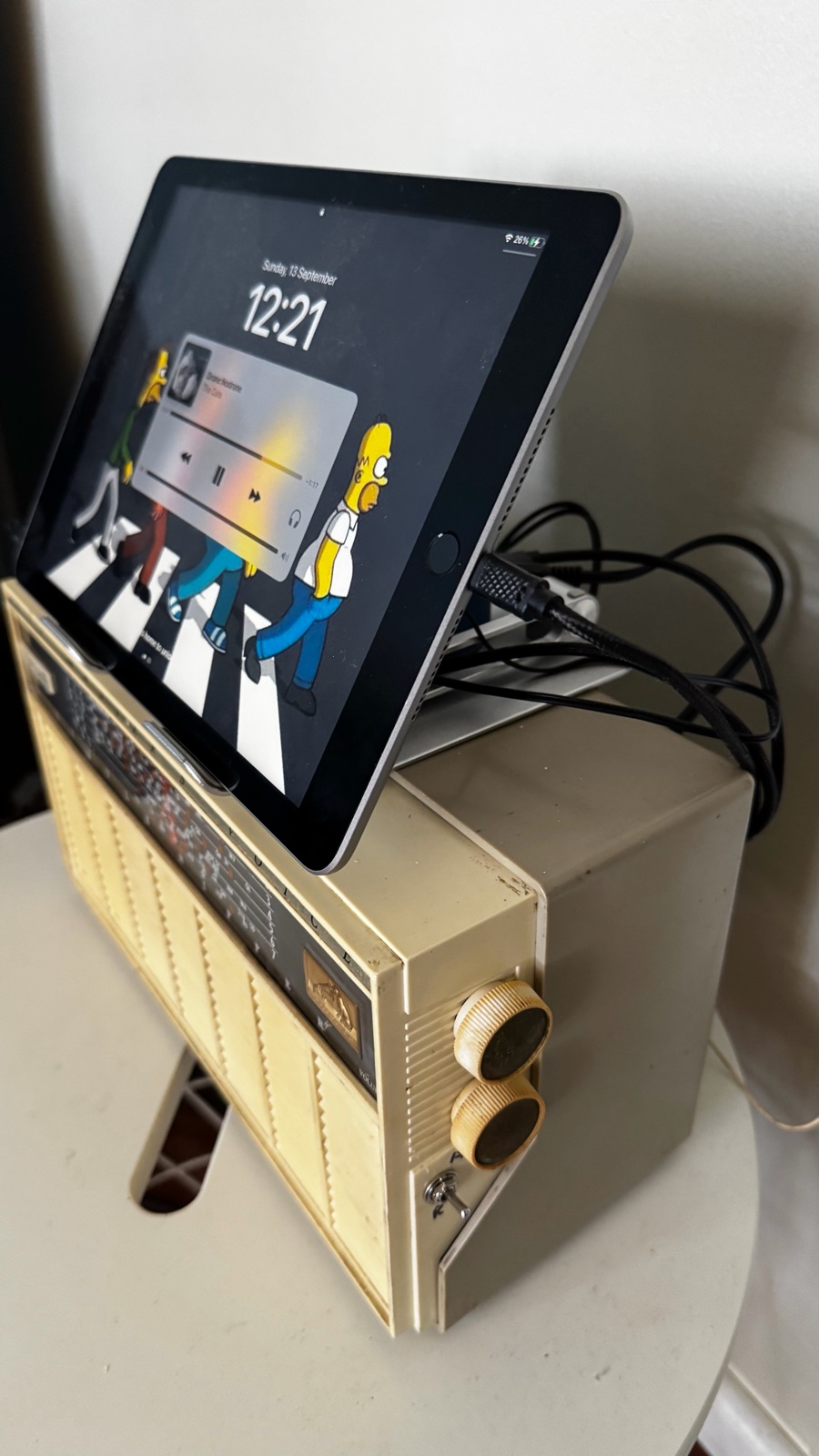 Finished: iPad → AUX → valves
What you’re building
There are two taps into the radio’s existing audio path. Neither replaces any original part, and both can be undone with a soldering iron.
AUX into the volume control
Music from a phone, laptop or Bluetooth receiver joins the radio just before the volume pot, which is the same place the AM detector feeds. From there it goes through the 6AV6 preamp, the output valve and the output transformer, just like a broadcast would.
Speaker or line out
A switch on the output transformer’s secondary sends the signal either to the original speaker or to a dummy load plus a line output converter (LOC). The LOC feeds RCA line level to a Yamaha amplifier’s AUX input.
A good learning project
One small build covers signal levels, impedance, DC blocking, RC filters, grounding and ground loops, inductive kickback, and how a superhet radio actually works. You also get a lovely-sounding speaker dock at the end.
What you’ll hear
The valve stages add the “warmth” people talk about. A single-ended output stage adds mostly second-harmonic distortion, which sounds musical and full rather than harsh. The small output transformer softens the top end and gently compresses peaks, and the radio’s audio stages were voiced for AM broadcasts, so the highs roll off early. The result is mellow, mid-forward and easy to listen to. It isn’t hi-fi, and that’s the appeal.
Tip: set the source to about 70–80% volume and use the radio’s own knob. A source at full volume can overdrive the 6AV6 grid and make it clip harshly.
How the radio works
The Super 5 is a five-valve superheterodyne. To pick the right tap points, you need to know the chain from the aerial to the speaker.
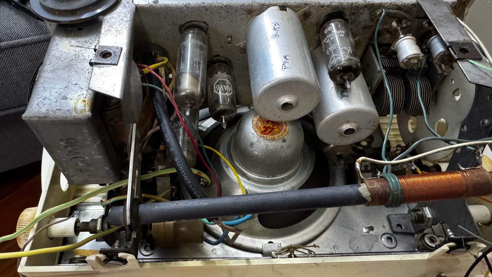 1
2
3
4
5
6
- 16AV6: twin diode (AM detector) and triode (first audio stage) in one bottle.
- 26BA6: IF amplifier pentode at 455 kHz.
- 3IF transformer cans: tuned filters that set the radio’s selectivity.
- 4Tuning gang: the variable capacitor the tuning knob turns.
- 5Ferrite rod aerial: the coil on the rod picks up the medium-wave signal.
- 6Speaker (Rola): the voice coil is fed by the output transformer.
Superhet in one paragraph
The converter mixes the incoming station with a local oscillator that tracks the tuning knob. Whatever station you tune, the result lands on one fixed intermediate frequency (455 kHz). The IF stage can then be tuned once at the factory for good gain and selectivity. The detector diode strips off the 455 kHz carrier and leaves the audio envelope. That audio goes through the volume pot to the triode, then the output pentode, and the output transformer steps the valve’s high-impedance drive down to suit an 8 Ω-ish speaker.
Safety first
⚠ Lethal voltages
Valve radios run at 150–300 V+ DC, and the big filter capacitors can stay charged after the set is unplugged. Many old radios have also been badly repaired over the years. If you’re not confident working around mains, get help from someone who is.
1 · Unplug, then discharge
Pull the plug, not just the switch. Wait, then use a meter to check the voltage across the main filter capacitors before you touch anything. Bleed them through a resistor (e.g. 10 kΩ 5 W on insulated leads) if they still hold charge.
2 · Is the chassis live?
Some sets were “AC/DC” with no power transformer, so the chassis itself is connected to mains. Most Australian mantel sets like this one have a proper mains transformer. Confirm yours does before you connect it to a phone or an amplifier. If it’s live-chassis, stop: every external connection would need isolation transformers.
3 · One hand, insulated tools
When testing a powered set, keep one hand off the chassis, use insulated probes and clip leads, and keep the bench dry and uncluttered.
4 · Never run without a load
A valve output stage must always see a speaker or a dummy load. Without one, inductive kickback in the output transformer can arc over and destroy it. This rule shapes the whole output design.
System design
Two selector switches, two small circuits. Blue marks new parts; the rest is original.
Concepts behind each part
Every part in this build exists for a reason you can work out. Here they are, with numbers.
Speaker level vs line level
Line level is what phones and amplifier AUX inputs use: about 0.3–2 V into an input of 10 kΩ or more, carrying almost no current. Speaker level is what the output transformer delivers: a few volts at hundreds of milliamps into about 8 Ω. A few watts into 8 Ω is about 4–6 V RMS, several times too hot for a line input, and the radio’s ground may not match the amp’s. A line output converter (LOC) steps it down (and often isolates it). Never feed speaker wires straight into an AUX socket, and never into PHONO, which has around 40 dB of extra gain and RIAA equalisation.
Why stereo can’t just be twisted together
A phone’s left and right outputs are two separate amplifiers. Tie them together and, whenever L and R differ, each one tries to drive the other. That means distortion, wasted current and stressed output chips. Put 1 kΩ in series with each channel and join the far ends, and the difference current is limited to a few mA. The 1 kΩ resistors cost almost nothing in level, because the next load is the radio’s volume pot of several hundred kΩ. A cheap “stereo to mono” cable is usually hard-wired with no resistors (the one checked during this build was), so don’t use it.
The DC-blocking capacitor is a high-pass filter
The capacitor passes AC (music) and blocks DC. That protects your phone if a fault ever puts HT on the volume pot, which is why it’s rated 630 V. Together with the pot’s resistance, it also forms a high-pass filter with corner frequency fc = 1 / (2π·R·C). Bigger C or bigger R gives deeper bass. Try it:
Second opinion on the AI advice
During the build, the AI assistant said a 10 nF or 22 nF cap would “cut off all your bass”. The calculator shows it depends on the pot. With a typical 500 kΩ pot, 22 nF gives fc ≈ 14 Hz, which is fine. 100 nF is still the right buy, because it leaves margin if your pot is smaller than expected.
Reading capacitor codes
Why a dummy load, and why 8.2 Ω is fine
Speaker + LOC
8 Ω ∥ ~1 kΩ ≈ 7.9 Ω. The LOC barely loads anything, so the transformer sees what it was designed for.
LOC alone
~1 kΩ or more is close to an open circuit. On loud peaks, the energy stored in the transformer has nowhere to go, the voltage spikes, and the windings or the valve can arc over.
8.2 Ω 10 W + LOC
A power resistor stands in for the speaker. 8.2 Ω is the nearest standard value, and real speakers swing well above and below 8 Ω anyway. 10 W covers a few-watt output stage with plenty to spare.
Bill of materials
Everything came from a local Jaycar plus parts already on hand. Prices change, so none are listed.
| Part | Qty | Spec | Job |
|---|---|---|---|
| A · Input (AUX → volume pot) | |||
| Metal-film resistor | 2 | 1 kΩ, ¼ W or ½ W (1.2–2.2 kΩ also fine) brown-black-black-brown-brown | Stereo-to-mono summing without shorting L and R |
| Film capacitor | 1 | 100 nF 630 V DC, polyester “greencap” or MKT, marked 104K2J | DC block / HT protection for the source |
| Toggle switch S1 | 1 | Sub-miniature SPDT (ON-ON), or one half of a DPDT such as Jaycar ST0310 | Radio / AUX selector |
| 3.5 mm stereo lead | 1 | Any plain AUX cable, cut to expose L, R and ground | Input lead |
| B · Output (transformer → Yamaha) | |||
| Line output converter | 1 | 2-channel, high-to-low, 7-wire (with power and remote leads) | Speaker level → RCA line level |
| Power resistor | 1 | 8.2 Ω (or 8 Ω), 10 W or more, ceramic cement or aluminium-clad | Dummy load when the speaker is switched out |
| Toggle switch S2 | 1 | Sub-miniature SPDT (ON-ON) | Speaker / line out selector |
| RCA lead | 1 | Stereo RCA–RCA | LOC → Yamaha AUX/CD |
| C · Consumables | |||
| Hook-up wire | ~2 m | Stranded, ~22 AWG, a couple of colours (shielded cable for the input run is better) | Links |
| Heat-shrink | 1 pack | 2–5 mm assorted | Insulate every joint and lug |
| Solder, tape, cable ties | Resin-core electronics solder | ||
| D · Optional | |||
| Stripboard | 1 | Small offcut, 16 × 11 holes | Tidier home for the input network (see Board) |
| Ground-loop isolator | 1 | 3.5 mm inline audio transformer | Kills buzz from laptops on chargers and mains-powered Bluetooth receivers |
| Bluetooth receiver | 1 | 5 V USB-powered, 3.5 mm out | Wireless input |
Shop-counter mistakes caught during the build
- 223K2J is 22 nF. It’s usable with a big pot, but 104 (100 nF) is the safer pick.
- 100 V caps: too low a rating for the inside of a valve chassis.
- X2 “across-the-line” caps: made for mains suppression, not signal paths.
- Hard-wired stereo→mono adaptor: no resistors inside, so it shorts L to R.
- ST0310 is ON-ON with no centre-off. For S2 that’s exactly what you want, since “off” would mean no load.
Input circuit (tap A)
Lift the detector wire off the top lug of the volume pot and put S1 in its place. Flip the switch below to follow the signal.
Which lug is which?
One observation from the build: the middle and bottom lugs share one cable. That’s the original shielded lead to the 6AV6 grid, with the core on the wiper (middle) and the braid on ground (bottom). The single wire on the top lug comes from the detector, and that’s the one you lift. Check with a meter, set unplugged:
- Ground lug: reads 0 Ω to the chassis.
- Wiper: its resistance to ground changes as you turn the knob, and reaches 0 Ω fully anticlockwise.
- Top (input) lug: reads the full track resistance to ground whatever the knob position. Write it down; that’s your R for the calculator above.
Output circuit (tap B)
S2 sits in the hot lead of the output transformer secondary. Position 1 feeds the speaker; position 2 feeds the dummy load and the LOC together, so the transformer always has a load.
Flip S2 at low volume
A toggle breaks before it makes. For a few milliseconds during the flip, neither the speaker nor R3 is connected. At low volume that’s harmless; at full volume it’s exactly the unloaded kick you’re trying to avoid. Turn the radio down before you switch.
The 7-wire LOC
| Wire | Car-audio meaning | In this build |
|---|---|---|
| White | Left in + | Twist with gray → S2 contact 2 (with R3) |
| White/black | Left in − | Twist with gray/black → ground junction |
| Gray | Right in + | Bridged with white, so mono reaches both RCA outputs |
| Gray/black | Right in − | Bridged with white/black |
| Red | +12 V power | Insulate, not connected |
| Black | Power ground | Insulate (try it on chassis only if you get noise) |
| Blue | +12 V remote turn-on out | Insulate, not connected |
If the RCA outputs stay silent with the power leads unconnected, your LOC has an active (powered) signal path. Feed red/black from a small 12 V DC plug-pack.
A tidier input board
The free-air build works. If you’d like something sturdier, the whole input network fits on a stripboard offcut of 16 × 11 holes.
| Strip | Net | Connections |
|---|---|---|
| A | L in | Tip wire at A2 · R1 top lead at A5 |
| E (left of cut) | SUM | R1 at E5 · R2 at E7 · C1 lead at E9 |
| E (right of cut) | OUT | C1 lead at E13 · wire to S1 pin 3 at E15 |
| I | R in | Ring wire at I2 · R2 bottom lead at I7 |
| K | GND | Sleeve wire at K2 · wire to the pot’s ground lug at K15 |
Build, step by step
Tick as you go; your progress is saved in this browser. Don’t move on from a phase until its gate passes.
0 · Make it safe and document it
bench · 20 min1 · Identify the lugs and wires
multimeter · 15 min2 · Build the input network
bench · 30 min3 · Fit S1 at the volume pot
chassis · 30 min4 · Output switch, load and LOC
chassis · 45 min5 · Power-up tests
powered · carefulBuild log
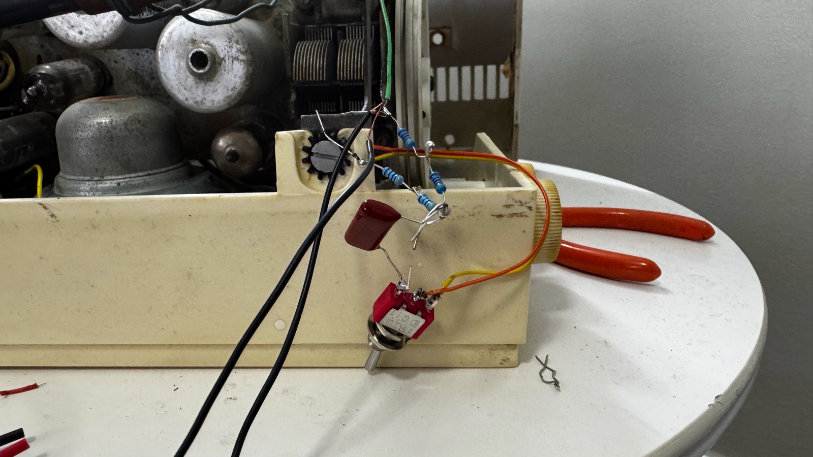
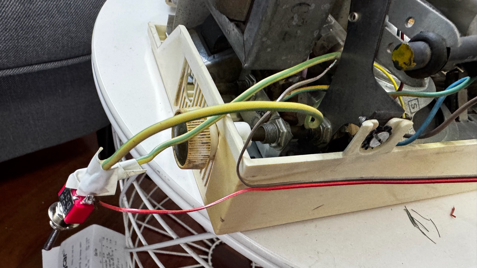
Going wireless
A USB Bluetooth receiver plugs straight into the AUX network. The harder question is where its 5 V comes from.
Separate USB supply or power bank
Use a good-quality, fully isolated 5 V USB plug-pack outside the radio, or a power bank. There’s no new mains wiring inside the cabinet and no extra load on the 70-year-old transformer. If it buzzes, add a ground-loop isolator.
USB charger wired inside
A small certified USB charger wired after the radio’s switch and fuse turns on with the set. Mains wiring must be insulated, strain-relieved and enclosed. If you’re not sure, don’t.
Tapping the 6.3 V heater winding
It can be done (rectify, filter, regulate), but the heater circuit is usually grounded on one side or centre-tapped. A bridge rectifier then fights the audio ground, and the hum often gets worse.
The no-solder alternative: an AM transmitter
A tiny AM transmitter (with a built-in Bluetooth receiver, or a separate one) broadcasts on a free spot of the dial, about 1–2 m range. Tune the radio to it. Nothing inside the set changes, and the sound still passes through every valve. Expect AM bandwidth (roughly 5 kHz) and some interference. A car FM Bluetooth transmitter can’t be converted: it works at 88–108 MHz with FM modulation, about 100 times higher in frequency.
Hum, buzz and other noise
On first power-up this build had a loud “current noise”. Start with two questions: does it change with the volume knob, and is it there on RADIO as well as AUX?
| Symptom | Likely cause | Fix |
|---|---|---|
| Loud 50 Hz roar in AUX that rises with the volume knob | AUX ground not connected, or the input wire open, so the grid is floating | Re-solder the sleeve/ground to the pot’s ground lug. Test: clip the AUX ground to the chassis and see if the roar stops. |
| Buzz or whine only when the laptop is charging, or the BT receiver is on mains | Ground loop: radio ↔ source ↔ mains earth (↔ Yamaha) | Run the source on battery to prove it, then fit a 3.5 mm ground-loop isolator before the 1 kΩ resistors. |
| Hum appears only with the Yamaha connected | Ground loop through the RCA shield | Try the LOC’s black lead on chassis, or not. Use an LOC with isolated outputs, or an RCA ground-loop isolator. |
| Hum in AUX, quiet on RADIO, with a long plain wire run | Unshielded high-impedance wiring picking up the heater or mains field | Shorten the runs, or use shielded cable (braid grounded at the pot end only). Route away from the heater and mains wires. |
| Hum on RADIO and AUX, unaffected by volume | Tired electrolytic filter caps (100 Hz ripple). This was there before the mod. | Recap the power supply. That’s a separate, worthwhile restoration job. |
| Thin, bass-light sound | DC-block cap too small for your pot | Check with the calculator and use 100–220 nF. |
| Harsh, clipped sound | Source too hot for the 6AV6 grid | Turn the source down to about 70% and use the radio’s knob. |
| Nothing from the Yamaha | S2 in position 1, wrong input chosen, or an active LOC with no power | Check S2 and the AUX input selection, or power the LOC from 12 V. |
Glossary
- Valve (tube)
- A vacuum device where a heated cathode emits electrons and a grid controls the current to the anode. Small grid voltage changes produce big anode changes, which is amplification.
- HT / B+
- The high-tension DC supply (150–300 V) that feeds the valve anodes. It’s the dangerous part.
- Superheterodyne
- A receiver that converts every station to one fixed intermediate frequency before amplifying and detecting it.
- IF
- Intermediate frequency: 455 kHz in Australian AM sets.
- Detector
- The diode stage that recovers audio from the AM carrier. Here it’s inside the 6AV6.
- Output transformer
- Matches the output valve’s high impedance (kilohms) to the speaker’s low impedance (ohms).
- Impedance
- AC “resistance”. Sources want to see the load they were designed for.
- Line level
- About 0.3–2 V signal into a high-impedance input. The language of AUX, CD and tape inputs.
- Speaker level
- The amplifier’s output: several volts at real current into roughly 4–16 Ω.
- LOC
- Line output converter. Steps speaker level down to line level, usually with RCA outputs.
- Dummy load
- A power resistor that stands in for the speaker so the output stage is always loaded.
- Flyback / inductive kick
- The voltage spike from an inductor when its current has nowhere to go. It’s why a valve amp needs a load.
- DC-blocking cap
- A series capacitor that passes AC audio but blocks DC voltage.
- High-pass corner
- The frequency where an RC filter is 3 dB down: f = 1/(2πRC).
- Ground loop
- Two or more ground paths between devices, forming a loop that picks up mains hum.
- SPDT / DPDT
- Single or double pole, double throw: one or two switches, each choosing between two contacts. ON-ON means no centre-off.
- Greencap / MKT
- Polyester film capacitors. Codes like 104K2J mean 100 nF, ±10%, 630 V.